Let's talk about electricity..

greybeard

Herd Master
Joined
Oct 23, 2011
Messages
5,940
Reaction score
10,803
Points
553
Location
East Texas
(am having problems staying connected today, so this may come out in bits and pieces)

This is about electricity in general, mostly regarding household current, safety, how electricity "works" and not about electric fencing, as hot wire fencing topics have been discussed multiple times over the years. As always, if I say something in error, especially from a safety standpoint, please DO correct me--I am not an engineer. (I just found the hat on the side of the road)

What is electricity? Well, it is in basic form, it is current flow. It occurs naturally, all around us, and of course produced by our regional or local energy provider.
That, is what it is. Now what is it NOT?
I have been surprised over the years by the number of people that think electricity is 'something' in and of itself. It is not an element, you won't find it on the Periodic table, it has no atoms or molecules. It can be stored, but you can never hold it physically in your hand, even if it couldn't shock you.

All the utility companies do, is begin the process of 'current flow' at their generators, and the rest is done by the atoms of the conductors between the generator and your house.

How does current flow? By movement of electrons that make up the conductors' atoms. I will use copper atoms since that is the most common conductor in our homes and farms. Copper atoms are made up of a nucleus containing protons, (a positive charged particle) Neutrons (no or neutral charged) and rings of electrons around the nucleus. Electrons are generally accepted top have a negative charge and as a result, are held in their respective rings by the attraction to the protons in the nucleus. (not always true, but for this discussion, close enough).

A copper atom:
copper%2029%205.gif


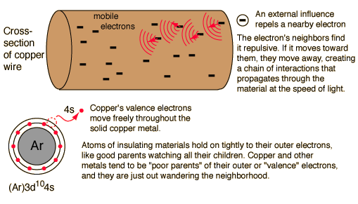
Now this isn't how an atom really looks, but it's how we present it for easier understanding and all we really need to look at is the outermost ring or shell where that single electron is. This is called the valence shell. Because of it's distance from the nucleus (and the attracting protons) the electron in the valence shell, is very loosely associated with that particular atom. It can be knocked off that copper atom by another particle. When it is knocked off, almost always by a valence electron from an adjacent copper atom, to moves immediately to the next copper atom, knocking that copper atom's valence out of it's shell to do the same thing to the next atom. This colliding of free electrons takes place in every conductor, even if not connected to a source field, such as a generator, but the free electrons collide in a random fashion, just bouncing around with no "sense of direction".
cond.gif


(electrons don't actually hit' each other tho. Each has it's own electromagnetic field, as one free electron approaches the free electron in another atom, the electromagnetic field of the 1st electron causes the free electron in the next atom's valence shell to move. Like charges repel, so an electron approaching another electron causes that approached electron to move out of it's ring and go to another atom.

When a utility company's generator begins to spin, an electromagnetic field in the output conductors is created, in one direction--down the line and eventually to the transformer in front of our homes. One valence (free) electron moving down the wires to the next atom. They are still bouncing or drifting somewhat randomly, but as a group, they now have direction.
This, is current flow. The movement of those free copper valence electrons from one copper atom to the next. (Now you see why there is no such thing as electricity in and of of itself. It's simply the movement of the conductor's own free electrons along that conductor.

How fast does electricity travel?
Dang fast. Ever had a power outage and even tho the problem may be many miles away, the millisecond the power guys throw the line switch back on, voila..your lights come on. The current flow (electricity) doesn't travel along the conductors at the speed of light, but pretty close to it..about 95% the speed of light. In a vacuum, it would travel at the speed of light , but in air, it does not, and movement along a resistive conductor, even copper slows it down only a little more, to about .
Light speed is generally said to be 186,000 miles per second.
Electricity in a copper conductor travels approx at 173, 984 miles per second, depending on conductor size, frequency etc. Still....very fast.

Now, tho it's obvious electricity moves at a high velocity, that doesn't mean the individual electrons themselves do. A snail would beat them in a race. A free electron drifts at the velocity of about 3 ft/hour, but because the copper atoms are so densely packed so closely together, it means movement from one atom's valence ring to another takes very little 'time', and the whole group of valence electrons within any measured length of copper conductor moves at 173,984 MPH.

Now, we know what electricity is, and how it 'moves' to our houses, farms and in the circuits of those homes and outbuildings.
I'll continue in another post.
 
Last edited:

greybeard

Herd Master
Joined
Oct 23, 2011
Messages
5,940
Reaction score
10,803
Points
553
Location
East Texas
Won't spend much time on electrical power generation, but here's how it is in basic terms. We will assume the generators are AC tho more and more utilities are using High Voltage Direct Current because DC suffers less loss over long distances.
A regional generator may create 30,000 volts. (30kV)
Right out of the generation station, a step up transformer increases that voltage to several hundred thousand volts--we'll use 500kV. This allows transmission of plenty of voltage to the surrounding customer base at less voltage loss and less cost to the utility. This is usually 3 phase, meaning 3 hots and a neutral on a "high line".

Along the way, closer to the customer base, a substation will tap those high voltage lines and step down the voltage to around 70kV, tho that 70,000 V figure will vary. Still 3 hots and a neutral.

(at some point here, a system neutral may be used, meaning there isn't a physical neutral wire on the poles. A big ground rod is used with an underground gridwork to ensure earth ground out to different substations and sub-grids--it uses the moisture in the earth as a conductor)

Another substation, and the voltage is dropped by step down transformer to a local (mostly) standard of around 7, 200 volts. It's not always 7200V, but it is in front of my pl;ace so that's what I'm going to use.

This is where a lot of variation happens. As the grid spreads out to different big circuits, individual taps are made off those 3 hot cables, but not all taps go to the same local user base. The utility balances their load by trying to tap equal voltages off each line as the big line moves accross the countryside and into towns. One subdivision may get tapped off line1, another from line2, the next from line3 etc.. The important part of this, is that the neutral is always present in some form, with only a few exceptions (which I won't go in to.)
Electricity-from-plant-to-distribution-transformer-to-home.jpg


In front of your home:


This will vary, depending how many end users/customers are on your local line circuit and if it also feeds businesses with higher energy needs than just residential homes. Some places, there may be 4 lines (3 hots and a neutral), other places there will be 3 lines running along the poles, (2 hots and a neutral) while other places just 2 lines,-1 hot @ 7200 volts and a neutral, and sometimes, just one line, tho that's rare today. It means the single 7200 hot line transformer in front of your home steps the voltage down to 2 hots of 120V each and centertaps a neutral for your home use. In almost all cases, the residential transformer will have a neutral centertap because voltage is always and in our case, can only be expressed as a potential in reference to ground/neutral. For those of a curious mind, a simple diagram explains it, tho the transformer connections are much more involved than what this shows.

transformerdiag.jpg


Why does it refer to the neutral as ground?
Because that neutral wire is grounded to earth at the transformer pole. Generally, a bare wire capable of carrying 200amps of current goes down the side of the pole before the pole goes in the ground, is stapled to the sides, and the end of the bare copper conductor is coiled in spirals around the flat bottom of the pole and that too is stapled in place.
http://waterheatertimer.org/images/power-pole-photo-2-23-4.jpg[img]
This, is not your home ground rod--it's the electric company's ground for the transformer and stray voltage.
We now have voltage headed for your house, in the correct voltage, as well as a neutral, and that neutral is very very important.
 

greybeard

Herd Master
Joined
Oct 23, 2011
Messages
5,940
Reaction score
10,803
Points
553
Location
East Texas
Lt Chekhov..take us into the neutral zone..
The neutral wire coming from the transformer and into your house is the same size as the 2 hot wires, but except when something is amiss, it carries no voltage. With everything off in your home, the 2 hot wires have voltage present, but zero amps. Amps is a product of work being done. The neutral tho, carries amps back out of the circuit. Without the neutral (in most cases) nothing will work correctly in your home, even tho voltage is present and measurable at you distribution box's wire lugs.

Neutral is completing a huge circuit, back to source, again, as illustrated in the diagram of transmission from generator to your home.

Remember, voltage potential, and as a result, current flow are referenced in relation to neutral. Without the neutral, those free electrons have nowhere to go, and they will stop moving down the copper conductors. "Stuff" stops working.
When distribution panels are purchased, they are purchased according to service provided, usually 200amp service. No one says, "I have 240 volt service to my house--they say "I have 200 amp service to my house" and that is because of the wiring in the mains is sized to safely carry that much load without burning the insulation off or tripping the main breaker. Again, there should be zero or very very little voltage on your neutral line--that big cable doesn't even go thru your power meter's measuring equipment--it bypasses it, either around the meter or back behind it.
Your electric usage is registered by the meter in power used (watts) which is obtained by multiplying Volts X Amps. Since there is virtually zero volts present in the neutral wire, there is no need it going thru the works of the meter.

So what is the big difference in a ground wire and the neutral wire?
If you didn't have a ground rod outside your home, with a big wire leading from the ground bus in your disconnect panel to the rod, your 'stuff' would still work, but it would not be safe. Even less so if you lost your neutral and had a short to ground in your equipment or devices.
For 200Amp service, the mains (hot and neutral) are 2/0 in size. But, the ground wire going from the meter base and your ground bus in the dist panel is only going to be #4 or #6. (Scotty--shields UP!)
If your neighbor loses a neutral, guess where it's likely going to backfeed to?
Your ground rod. Since you still have a neutral, you will probably be ok other than a few blown light bulbs.

Looking at the pictures and diagrams I posted, you can see several places where neutral is bonded to earth ground. In your homes' distribution panel (according to NEC) this happens @ the first point of disconnect in your home) the neutral bar and the ground bar are physically bonded together as well.


It would seem that neutral and ground are the same thing, and they are similar, but major differences exist. Again, the neutral wire even in branch circuits is the same size as the hot wire(s) because it has to be able to carry all the amps the circuit and it's load creates. The ground wire tho, in devices and equipment is usually 1-2 sizes smaller than the hot(s) and the neutral. And, even in Romex, the hots and neutral are individually insulated then contained inside a thin outer sheath, with the ground wire not individually insulated except in some 4 conductor romex. (Usually for 240volt appliances) That outer sheath, should the ground wire have to carry all the amps back to the ground bus to get to neutral is a common source of burning insulation, because as the electrons move along the wire, they predominantly move only along the outer circumference of the copper conductor. The center of the conductor sees very little electron movement, so the outer 'skin' of the conducter gets hotter faster. The ground wire is simply there to provide a safety net..to prevent shock from a short to equipment case and housings. Do not, use ground wires for neutral or neutral to take the place of ground wires.

This, is IMO, a bad practice:
shapeimage_1.png


Altho it is allowed by some local codes to have more than one ground wire (up to 3 I think) in the same terminal hole, and you can intermingle ground wires and neutrals in the same bus bar as long as it's in the main panel.
Still, something like the above photo makes trouble shooting very difficult and can interfere with proper circuit protection operation (breakers and fuses) . You would of course, trip the branch circuit in question, but in the above scenario, have to disconnect multiple grounds and neutrals to isolate a problem and those uninvolved disconnected neutrals and grounds can cause an over voltage problem in a working circuit.
If this were a sub panel (out in a barn or shed, it violates the rule about joining neutral and ground ONLY at the first means of disconnect. In sub panels, you never join neutral and ground together. Why? Usually, the supply conductors for a sub panel in an out building are smaller than the mains coming in to your main distribution panel. IF you lose ground or neutral at your main panel, the next direct source to neutral will be your subpanel feed wires, and as was stated, the neutral coming into your home has to be able to carry all the amperage the two hots can. That sub panel and it's wiring cannot usually do so.


*(neutral and ground wires in same bus of main dist panel won't pass electrical inspection where I live.

Next, circuit protection..
 

greybeard

Herd Master
Joined
Oct 23, 2011
Messages
5,940
Reaction score
10,803
Points
553
Location
East Texas
I need to add exceptions to the need for a neutral, and that is in some 240volt applications, especially motors, such as a submersible water well pump. Most are induction motors, and need only 2 individual lines of 120V each to run, and a ground wire for circuit protection. You will only be required to run a neutral if the 240 volt appliance uses one side of the line to power something that uses 120v..such as the lights on your kitchen range, or the electric motor that spins your dryer tub. The heating elements in those appliances are 240V but the ancillaries are 120V so a neutral is run in those instances.

In a strict 240V device (motor) the two 120V lines make up 240V line to line but since they are different legs, their created amps are cancelled by each other. If there is no place on the motor to connect a wire from your main neutral bus, then do not attempt to do so by running a neutral to case. The metal case is already going to be connected to a ground wire, and running a neutral to the case is the same as connecting ground to neutral, and again, that should only be done at the first disconnect device, which usually your main distribution panel.
 

greybeard

Herd Master
Joined
Oct 23, 2011
Messages
5,940
Reaction score
10,803
Points
553
Location
East Texas
Going to take a break now, but I want you to do something. Say:
"One one thousand two one thousand"
or
"one Mississippi two Mississippi"
Each represents an approximate elapsed time of 2 seconds, and I'm going to use that time to debunk a common misconception regarding circuit protection and circuit breakers.
 

greybeard

Herd Master
Joined
Oct 23, 2011
Messages
5,940
Reaction score
10,803
Points
553
Location
East Texas
Circuit protection in homes and outbuildings...
I am not going to get into specifics, as there are just too many ways to achieve the same protection, and too many options out in the marketplace.

Most of us, if we live in a home that is less than 50 years old, have circuit breakers instead of fuses in our distribution and sub panels, so breakers is where I will start.
The main breaker, or outside disconnect is sized according the the Service you have available--in Amps. For most of us, that will be 200amps. Now, most of us will not use 200A in our daily lives at home or on our farms, so why the rating that high?
It goes back to the name of what I'm discussing Circuit Protection. The cable feeding our homes is rated to handle 200A (plus a safety margin) and as part of the overall circuit, that is the maximum capability of the main allowed. (remember; neutral is a return path for the current our loads create, so it is also part of our circuit and @ least theoretically, has to be of a wire size to carry 200A)

One of the misconceptions people have about breakers and fuses, is that they are there to keep us from getting electrocuted. I've heard it time and time again and that, is mostly BS. It's right in the name; Circuit Protection. It doesn't protect us, it doesn't protect our appliances or devices--it protects the circuits and their primary supply and return paths. It's to help prevent our homes and outbuildings from burning down. There are newer breakers that do a better job towards protecting people, but still, their primary function is to protect the CIRCUITS.

Let's look at that a minute. How do we know what size breaker to use?
We have a circuit, with some 120V wall double outlet receptacles on it in a bedroom. National Electric Code (NEC) says for bedrooms and living rooms, there should be a receptacle at minimum, one 6' from any corner or doorway and on a straight wall, no farther than 12' feet apart. That, for most bedrooms means at least one on every wall. Rule of thumb is 10 receptacles per 15 amp circuit or 13 receptacles per 20 amp circuit. (assuming a 1.5 amp load per plug)
(Warning..there is nothing simple or user friendly about the NEC. They live for exceptions, ambient temperature insulation violations, terminal connectiors versus conductor ampacities and everything else you can think of)

So, we now know what our possible load for that bedroom is and therefore know what size wire has to be used. You size the breaker according to the wire used in that circuit, which for 20amps, is 12ga.
How do we know that?

Wiring is rated by the manufacturer according to the capacity to carry current (amps) and that rating is called 'Ampacity". What determines ampacity? The diameter of the conductor, the material making up the conductor (copper vs aluminum) and the heat tolerance rating of the insulation around the bare conductor and the number of conductors if in conduit or raceway as opposed to being run in open air. Fortunately, we don't have to do a lot of research to determine all that..it's done for us.

Notice the notes at the bottom referring to ambient temps? If you are running romex from dist panel, up thru an attic and down to a bedroom, that attic space's temperture becomes the ambient temp even if it's only part of the circuit. If the attic routinely gets over 140 deg F, are supposed to use a better insulated conductor. If unsure, consult a certified electrician!
31015b16.jpg


ampacitychart.jpg

NM-B is romex, & is what is used in most homes today. As you can see, It's rated ampacity is 20A, so that is the wire size we would use in our bedroom, assuming we haven't stuck a big honking window air conditioner in there and run it off the same circuit as all the other things we are powering.

So, what size breaker to use?
20Amps. You always size the breaker according to the smallest wire in the circuit.

But the other part of that, is how did we come to decide we used #12 wire?
We decide that, according to the normal things that would be used in that circuit, and everything should have a rating on their data plat or label. You add them all up and that's the total amps you would ostensibly require of that circuit. For instance, the 3 bulb lamp on my computer desk is rated for a maximum of three 60 watt incandescent bulbs. 3 x 60=180watts. (not incandescent? squigly bulbs or LEDs?It doesn't matter if I use a newer type bulb or not, power is power, so use whatever the wattage is of the type bulb screwed in the sockets.

Uh Oh, problem. Data labels almost always come stated in power used which is in Watts. No problem.
We know the voltage (120V) and we know the Watts. So, we can calculate the amps by I(A) = P(W) / V(V).
Watts ÷ Volts=Amps.
(there is technically, another part to that calculation, called the power factor, but 'most of the time', for household small appliances, it is a factor of 1 or less so it is not as important as getting the voltage and watts entered correctly)

some common appliance ratings in watts:
(in general)
https://www.georgiapower.com/in-your-community/electric-safety/chart.cshtml
https://www.daftlogic.com/information-appliance-power-consumption.htm

So, we add up all the generally used devices' wattage or everything we think we might use in the future on that circuit, convert the total to amps and we then know how to size the wiring for the bedroom circuit.
Now, 20A is a LOT--it's 1/10 our total amperage available of 200 amps. Having said that, I've seen people try to add a big window unit into a bedroom's circuit mix when their central unit went out and use 1/2 the 20 amp rating of that bedroom's circuit. Just looked at a 120 v 15,000BTU window unit for the heck of it, energy star rated and it pulls 11.8 amps. Something like that needs to be on it's own dedicated circuit.

Ok, we have our typical room circuit and we have a circuit breaker to match it. Something happens a the breaker starts tripping, and we can't figure out what is causing the problem. If you are versed in electrical basics, you can probably find it on your own, but if not, call an electrician. Do NOT put a larger sized breaker in that circuit's slot!! It's a good way to find out in a hurry, just how long it takes the nearest volunteer fire dept to reach your farm.
 

greybeard

Herd Master
Joined
Oct 23, 2011
Messages
5,940
Reaction score
10,803
Points
553
Location
East Texas
Now, I explain why I decided to post this.

I have heard plenty of spoken and seen several myths regarding electricity posted all over the web, including a couple here at BYH.

I recently read a discussion regarding a little girl's electrocution when she came in contact with a bare (non-insulated) live 120V wire outside a neighbor's home. The detailed history behind the unfortunate death is irrelevant to this thread, but the basics and one of the comments about the death is.
The wire was stuck into the hot side of a residential 120v AC 20Amp circuit receptacle, protected by standard 20A circuit breaker. That's all I want to say about the basics of that event.
The comment that shocked me, was from an adult almost as old as I am and he should have known better:
"I wonder why the breaker didn't trip--it should have."
No, it 'may' have, but unless the fault to ground thru her body was in excess of the amp rating on the breaker, it would not have, and even if it eventually had, she would most likely have died anyway by the time it tripped.
How does a CB (circuit breaker) work?
There are different kinds, but the simplest ones, and the ones most of us are familiar with work by way of a bi-metallic strip. In overload conditions (amps beyond the CB's rating), the bi-metallic strip heats up, bends or contracts in a slight 'U' and in doing so, shortens, which makes it release a catch to the switch inside the breaker housing.
http://www.southlandelectrical.com/how-circuit-breaker-works.asp

A different kind, but the CB still has to sense a high amp use before tripping:
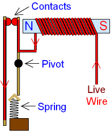
When the live wire carries the usual operating current, the
electromagnet is not strong enough to separate the contacts.
If something goes wrong with the appliance and a
large current flows, the electromagnet will pull hard enough
to separate the contacts and break the circuit.
The spring then keeps the contacts apart.

circuit-breaker.gif


Yet another one, very close to how what we call a GFI operates, that works a bit better and faster. Note the importance of the neutral line and the appliance's ground wire:
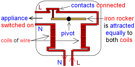
This type of circuit breaker (Residual Current Breaker) works by comparing
the current going in to an appliance with the current coming out.

When an appliance is working correctly
all of the current entering the appliance through the live wire
is returned to the power supply through the neutral wire.

In the picture below the strength of the magnetic field is the
same in both coils because they both have the same current.

rccb.gif


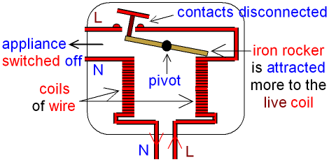
If something goes wrong with the appliance
some of the electric current will flow through the earth/ground wire.
The amount of current flowing through the neutral wire
decreases and now there is a difference between the
current entering the appliance through the live wire and the
current returned to the power supply through the neutral wire.
This difference is called the residual current.

The coil connected to the neutral wire now has a
weaker magnetic field than the coil connected to the live wire.
The iron rocker turns about the pivot and the
contacts are disconnected which switches off the
appliance and makes it safe.

rccboff.gif

The RCCB acts to switch off
the electricity much faster than a fuse or MCB.

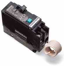
We now have breakers that incorporate both the bimetallic strip and the technology of the RCB/GFI in one housing, but they are pretty expensive and some won't fit standard distribution panels. They are called Arc Fault Circuit Interrupters or Arc Fault Circuit Breakers. They protect both the circuit and do a much much better job of instantaneously protecting devices/equipment and "Us".

They often look like this, but some are bigger and have the coil neutral pigtail hidden. They are connected to the hot bus, the neutral bar and to the neutral of the circuit they are protecting and monitoring--there's that neutral thing again--it's much more than "just another ground wire":
afcii.jpg

Inside an AFCI that doesn't have a test button (now required by NEC)
SD_AFCIb.JPG

Note the little electronics board.
How do these work?
It's...complicated, but the short answer is the AFCI has electronics inside that monitors what is known as sine waves, which you've undoubtedly seen on a science fiction show on an oscilloscope.
The 2 wavy lines that go up and down below a centerline of a screen. The wave changes every cycle of current flow--cycle meaning the change of direction that AC makes 60 times each second. When an arc occurs, it disrupts the sine waves and the AFCI detects this and electronically kills the circuit.
Figure-1.jpg


As of 2014, NEC, on all new construction and remodeling, requires AFCI for almost all areas of your home, except bathrooms, crawl spaces, attics, garages, and outdoors.
You can read more about them here, altho the article does predate the changes to NEC in 2014:
http://www.ashireporter.org/HomeInspection/Articles/AFCIs-Come-of-Age/2418
 
Last edited:

Baymule

Herd Master
Joined
Aug 22, 2010
Messages
33,470
Reaction score
100,489
Points
873
Location
East Texas
This is very educational. My comprehension of electricity is about as clear as mud. I now have a glimmer of understanding. Thank you.
 

greybeard

Herd Master
Joined
Oct 23, 2011
Messages
5,940
Reaction score
10,803
Points
553
Location
East Texas
Remember I asked you to say "One Mississippi" or "One one thousand" ?
Each of those takes approximately one second say in a normal speaking voice.
Another misconception I see all the time and have heard since I was very young:
"AC will knock you off the wire and DC will grab you and hold you"
That, is a load of rubbish, or at least the AC part is. DC will more or less hold you, because the electrons are moving in one direction, toward the negative potential, but AC will hold you no less than DC will.

Take your hand, open it up palm up, and close you fingers together as fast as you can, while saying one of the above phrases. IOW, how many times can you open and close you fingers against the wrist side of your palm in one second?
6...maybe 8 times?
IF, AC current here in North America cycled back and forth once per second, 'maybe' you would be knocked off it, but the electron train cycles 60 times in one second--every second--and that is a complete cycle. IOW, positive to negative and back to positive in 1/60th of a second. WAY faster than you can make your hand open...

14r9pe.jpg

BUT WAIT! There's More!
What I said above isn't really how it works.
Didn't really want to go too far, but here's how AC @ 60 Hz (cycles) works:
The switch is off--there is no voltage and therefore no current. The electrons are at zero voltage.
On an O'scope, the cycle begins at the midline.
We use 60 hertz (cycles per second) in North America and the direction changes twice within a cycle, and they do it 60 times in one second so therefore, the electrons and current changes direction 120 times in one second.
The following image shows one complete cycle between the dotted lines. You can see the 2 changes in direction within that cycle.
tim1.gif


So, the premise behind the "AC will knock you off it" is the belief that as the electrons change directions, the current stops and reverses polarity and it will release your muscles. It Might....... if we operated our AC @ one cycle, or slower-- less than 1Hz, but we don't. The interval that a 'release' might take place isn't at 1 second, or 1/60th of a second but instead, it is at 1/120th (one one hundred twentieth) of a second. As good as our eyes are at distinguishing events and movement, as fast as our human brains are at interpreting those events, we don't even notice that our incandescent bulbs in reality, are blinking on and off at a very high rate of speed. No muscle on our body works at anywhere close to that speed.
Heck, a hummingbird wing only flaps at a rate of 70 strokes/second and we can't even see that as anything other than a blur.
IOW, the changes in polarity of AC current happens so quickly that we 'feel' it as one continuous pulse, and won't "get knocked off it". Just another old wives tale.
Now that we see how our household stuff works ......
Next up, is:
How does this come into play "down on the farm".
 
Last edited:

Latest posts

Top